Forskjell mellom versjoner av «Laser-rotary axis»
(→Prepare laser) |
|||
| Linje 24: | Linje 24: | ||
* Run the laser head to top right corner | * Run the laser head to top right corner | ||
* Lower the bed… a lot (U-) | * Lower the bed… a lot (U-) | ||
| − | |||
* Move laser head approx half way on the y axis | * Move laser head approx half way on the y axis | ||
* TURN OFF the laser before opening the the bottom panel on the right side of the laser | * TURN OFF the laser before opening the the bottom panel on the right side of the laser | ||
Revisjonen fra 8. jul. 2022 kl. 13:41
Innhold
Important…
NEW guidelines: When installing the rotary axis inside the laser, place it with the chuck (spindle, heavy end, jaws, grip) to the LEFT. Why? Should you turn off and on the laser, the laser head will attempt to "home". Since one axis is now rotating, and only one axis moves the laser head, it will then "home" to the far right. IF the rotary axis thingamabob is placed with the chuck to the right, the laser head will crash into the chuck and potentially be seriously damaged.
Prepare files: formulae
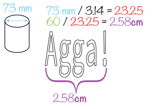
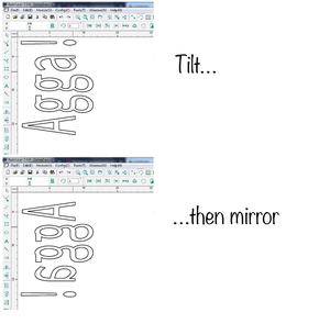
The object is round. It spins at a certain speed depending on your settings. To account for this, the artwork needs to be "distorted" in the software so it will turn out correctly on the object. You need to know:
- Diameter of the object (at the place where you will engrave/cut)
- Length of the artwork
drawing width/(object diameter / 3.14) = drawing width to use in autolaser
Example
Prepare laser
- Run the laser head to top right corner
- Lower the bed… a lot (U-)
- Move laser head approx half way on the y axis
- TURN OFF the laser before opening the the bottom panel on the right side of the laser
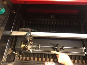
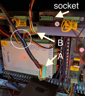
- Swap connectors behind the panel (see image).
- Basically: there are two connectors (A and B) attached to each other (or rather: they come out of the same twisty-cable-holder-thing), and one is plugged in to the socket.
- Swap them
- Close the lid
- ALWAYS PUT the normal one BACK when finished. If someone didn't attend the Rotary-attachment training, they'll have NO idea why the laser isn't working.
- Turn the laser on. It should now be unable to "home" normally (go to the top right corner), as one axis now is the rotary, but will "home" on the Y axis, sending the laser head all the way over to the right side.
Rotation max/min
Even if the rotary attachment has no physical endpoints, the laser control software will have a max/and min position. You will probably want to do your work while the laser is in the middle of these points. This can be achieved by rotating the attachment using the up/down button to one end, counting the number of seconds it takes to rotate all the way to the other end, and then rotating it back approx half as many seconds as a max-min-movement takes. If you try to range or start a job while the laser is to close to the max or min positions you will get a outbound (out of bounds) error on the display panel.
"Jaw"
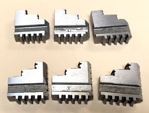
Decide which teeth you need. There are two types, each a set of three: expanding and contracting. The expanding secures the object to the spindle by pushing from the inside out. (for concave glasses) The contracting ones secures the object to the spindle by pushing from the outside in. (for convex glasses)
Both the expanding (inner diameter of work piece) and contracting (outer diameter of work piece) teeth have a work area (max/min diameter) of approx. 2.5cm to 7.5cm.
They are numbered, and marked:
- X for expanding (best for concave objects ends)
- O for contracting (best for convex objects ends)
How to attach
The teeth and the chuck key should be in a dedicated box on the tall shelf behind the door.
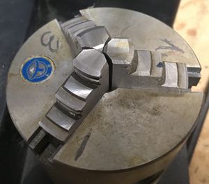
- To attach the teeth, place each of the three teeth in their correspondingly numbered slits 1, 2, 3.
- The pointy end goes in towards the center (so that when fully tightened it forms a compact shape of three triangles)
- Hold them in place with one hand, with a finger on each.
- Use the chuck key and screw OUTWARDS. ONLY use the special chuck key that came with the rotary axis.
- Keep screwing outwards until you feel number one click.
- Keep screwing outwards until you feel number two click.
- Keep screwing outwards until you feel number three click.
- Here is the surprise: Keep screwing outwards until you feel number one click again.
- Gently start screwing inwards.
- Screw all the way in, and visually check that the teeth align perfectly in the center. If they don't, your material will rotate off center, and potentially break your material, the attachment and/or the laser head. So if they don't line up perfectly, do it again.
Place the rotary axis attachment inside the laser
- Carefully place the rotary axis attachment inside the laser with the jaws (spindle, chuck, heavy end…) to the LEFT.
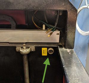
- Attach the coax cable from the rotary axis attachment to the connector inside the laser. When you stand in front of the laser, it is bottom right. The connector is marked with a yellow sticker: "rotary pinboard" (see image).
- From now on you must be VERY careful not to smash the laser head into stuff
Align the probe over the desired area and set focus point as normal, with .+enter.
To be super careful, drive the laser head away from the rotary axis attachment, and do a range test in an area where it will not smash into anything, should there be a … mishap. Pay careful attention to how the probe moves, and how the rotation moves. If it seems as expected, drive the laser head to the place where you want the job to begin. Note that you do not align with the probe, but the laser.
Glass surface: Preparation
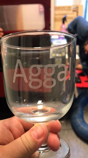
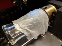
Using a moist paper towel helps prevent the engraving area from becoming rough, and leads to a clear, white engraving result. Before you start engraving, apply a moist single-layer paper towel to the glass. Make sure there are no air bubbles or overlaps. This would affect the engraved image.
We have so far had success with one ply from the two-ply towels from the bathrooms, damped liberally using a spray bottle (i.e. the fire-bottle in the laser room).
Do not spray water inside the laser.
Suggested settings
IKEA rødvinsglass, IKEA beer glass, IKEA tall beer glass raster: 100 mm/s 50%
