Forskjell mellom versjoner av «Laser-rotary axis»
| Linje 2: | Linje 2: | ||
# Switch the laser off. | # Switch the laser off. | ||
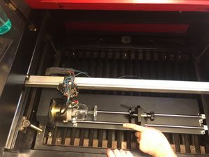
| − | # Open lid and place the rotary axis assembly on the bed, close to the upper left corner. Place the assembly with the chuck (spindle, heavy end, jaws, grip) to the left. This is important to prevent the laser head from crashing into the chuck during homing or reset, and cause damage! | + | # Open lid and place the rotary axis assembly on the bed, close to the upper left corner. Place the assembly with the chuck (spindle, heavy end, jaws, grip) to the left. This is important to prevent the laser head from crashing into the chuck during homing or reset, and cause damage! [[Fil:Placing rotary axis inside laser.jpg|center|thumb]] |
| − | |||
| − | |||
| − | |||
# Calibrate the vertical position of the assembly to the same distance on the left and right. | # Calibrate the vertical position of the assembly to the same distance on the left and right. | ||
# Connect the rotary axis cable to the socket on the inside wall in the lower right corner. | # Connect the rotary axis cable to the socket on the inside wall in the lower right corner. | ||
| Linje 15: | Linje 12: | ||
=== Assembling the chuck === | === Assembling the chuck === | ||
| − | If you need to assemble or disassemble the jaws on the chuck | + | |
| + | If you need to assemble or disassemble the jaws on the chuck, observe the following. | ||
| + | Decide which teeth you need. | ||
| + | There are two types, each a set of three: expanding and contracting. | ||
| + | The expanding secures the object to the spindle by pushing from the inside out. (for concave glasses) | ||
| + | The contracting ones secures the object to the spindle by pushing from the outside in. (for convex glasses) | ||
| + | |||
| + | Both the expanding (inner diameter of work piece) and contracting (outer diameter of work piece) teeth have a work area (max/min diameter) of approx. 2.5cm to 7.5cm. | ||
| + | |||
| + | They are numbered, and marked: | ||
| + | * X for expanding (best for concave objects ends) | ||
| + | * O for contracting (best for convex objects ends) | ||
| + | |||
| + | ==== How to attach ==== | ||
| + | |||
| + | The teeth and the chuck key should be in a dedicated box on the tall shelf behind the door. | ||
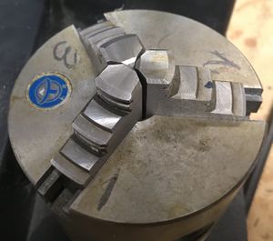
| + | [[Fil:Teeth lining up in the center.jpg|miniatyr|teeth align tightly in the center]] | ||
| + | * To attach the teeth, place each of the three teeth in their ''correspondingly numbered slits 1, 2, 3.'' | ||
| + | * The pointy end goes in towards the center (so that when fully tightened it forms a compact shape of three triangles) | ||
| + | * Hold them in place with one hand, with a finger on each. | ||
| + | * Use the chuck key and screw OUTWARDS. ONLY use the special chuck key that came with the rotary axis. | ||
| + | * Keep screwing outwards until you feel number one click. | ||
| + | * Keep screwing outwards until you feel number two click. | ||
| + | * Keep screwing outwards until you feel number three click. | ||
| + | * Here is the surprise: Keep screwing outwards until you feel number one click again. | ||
| + | * Gently start screwing inwards. | ||
| + | * ''Screw all the way in,'' and visually check that the teeth align perfectly in the center. If they don't, your material will rotate off center, and potentially break your material, the attachment and/or the laser head. So if they don't line up perfectly, do it again. | ||
| + | |||
| + | |||
== Forberedelser i Lightburn == | == Forberedelser i Lightburn == | ||
| Linje 105: | Linje 130: | ||
=== "Jaw" === | === "Jaw" === | ||
| − | |||
| − | |||
| − | |||
| − | |||
| − | |||
| − | |||
| − | |||
| − | |||
| − | |||
| − | |||
| − | |||
| − | |||
| − | |||
| − | |||
| − | |||
| − | |||
| − | |||
| − | |||
| − | |||
| − | |||
| − | |||
| − | |||
| − | |||
| − | |||
| − | |||
===Place the rotary axis attachment inside the laser=== | ===Place the rotary axis attachment inside the laser=== | ||
Revisjonen fra 7. apr. 2025 kl. 20:40
Setting up the rotary axis
- Switch the laser off.
- Open lid and place the rotary axis assembly on the bed, close to the upper left corner. Place the assembly with the chuck (spindle, heavy end, jaws, grip) to the left. This is important to prevent the laser head from crashing into the chuck during homing or reset, and cause damage!
- Calibrate the vertical position of the assembly to the same distance on the left and right.
- Connect the rotary axis cable to the socket on the inside wall in the lower right corner.
- Roll the whole laser forward from its normal position and open the compartment on the right side.
- Exchange y-axis power plug with rotary axis power plug. (The two plugs are connected with a common ground.)
- Close compartment. Roll laser back into its normal position.
- Switch the laser on.
- Beware that the bed must be lowered a lot with U-button when the rotary axis is used.
Assembling the chuck
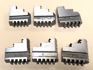
If you need to assemble or disassemble the jaws on the chuck, observe the following. Decide which teeth you need. There are two types, each a set of three: expanding and contracting. The expanding secures the object to the spindle by pushing from the inside out. (for concave glasses) The contracting ones secures the object to the spindle by pushing from the outside in. (for convex glasses)
Both the expanding (inner diameter of work piece) and contracting (outer diameter of work piece) teeth have a work area (max/min diameter) of approx. 2.5cm to 7.5cm.
They are numbered, and marked:
- X for expanding (best for concave objects ends)
- O for contracting (best for convex objects ends)
How to attach
The teeth and the chuck key should be in a dedicated box on the tall shelf behind the door.
- To attach the teeth, place each of the three teeth in their correspondingly numbered slits 1, 2, 3.
- The pointy end goes in towards the center (so that when fully tightened it forms a compact shape of three triangles)
- Hold them in place with one hand, with a finger on each.
- Use the chuck key and screw OUTWARDS. ONLY use the special chuck key that came with the rotary axis.
- Keep screwing outwards until you feel number one click.
- Keep screwing outwards until you feel number two click.
- Keep screwing outwards until you feel number three click.
- Here is the surprise: Keep screwing outwards until you feel number one click again.
- Gently start screwing inwards.
- Screw all the way in, and visually check that the teeth align perfectly in the center. If they don't, your material will rotate off center, and potentially break your material, the attachment and/or the laser head. So if they don't line up perfectly, do it again.
Forberedelser i Lightburn
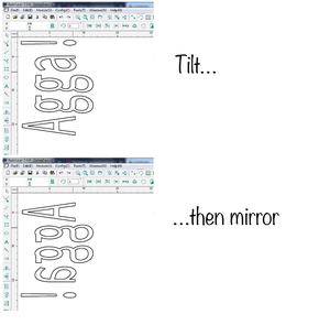
Rotér mot klokka og vend vertikalt
Designet må roteres 90 grader mot klokka for at det skal beholde naturlig orientering når rotary axis benyttes. Dette fordi rotary axis dreier rundt x-aksen, slik at designets bredde vil avtegnes i y-retningen. I tillegg må designet vendes i y-retningen, dette fordi det er godset og ikke laserhodet som beveges i y-retningen når rotary axis benyttes.
Med rotary axis vil laserens horisontale bevegelse tilsvare målene i designet (typisk opp-og-ned-retningen i designet), mens y-aksen påvirkes av at det brukes rotary axis og målene kan justeres under ett.
Én omdreining på rotary axis tilsvarer 101,7 mm
Det er fast for Bitrafs rotary axis at 101,7 mm langs y-aksen utgjør én full omdreining. En runde på 360 grader utgjør alltid hele omkretsen, og dette gjelder uavhenging av godsets radius. Designet skal derfor rett og slett skaléres til 101,7 mm, om det er tenkt at designet skal graveres hele veien rundt godset! Om du vil at designet skal utgjøre 1/3 av omkretsen, så skalérer du til 33,9 mm (1/3 * 101,7 = 33,9). I Lightburn gir dette fortegning – med mindre du tilfeldigvis skal lasre gods med omkrets på akkurat 101,7 mm!
Gods med varierende omkrets
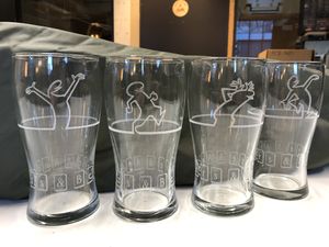
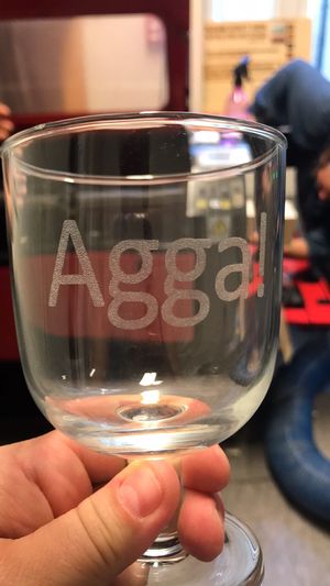
Det anbefales å legge alt design på ett lerret, som har reell høyde og bredde tilsvarende godsets omkrets der hvor det meste av graveringen skal skje. Fortegning kan ikke unngås når det graveres på gods som har profil med varierende omkrets. Fortegningen kan reduseres ved at designet deles opp i del-jobber der hvor det er stor forskjell i omkrets. Elementer som skal plasseres på breddegrader med avvikende omkrets må skaleres horisontalt så får samme samme bredde. Disse elementene blir seende fortegnet ut på lerretet, men blir bra under gravering – gitt at laseren fokuseres på nytt for hver omkrets. På glassene under, er største og minste omkrets på henholdsvis 264 mm og 199 mm brukt. I designet ble teksten strukket i den horisontale retningen fra 199 mm til 264 mm, for å bevare originalfontens proposjoner best mulig.
Styrke og fart skal ikke justeres
Egnet power for gravering i vanlig (billig) glass fra f.eks. IKEA eller Culina, er 20% med fart 100 mm/s. Styrke og fart skal ikke justeres i forhold til godsets omkrets, fordi man sørger for at laseren hele tiden holder fast avstand til godset, også når rotary axis benyttes. Dette sikres ved å fokusere laseren på nytt hver gang man skal gravere på steder med annen omkrets (så ofte som godsets profil krever det, og designet tillater det – én deljobb for hver omkrets).
Graveringstettheten må økes med større omkrets
Selve graveringen gjøres med horisontale linjer i én passering (dette må være valgt i Lightburn), men det er viktig at linjetettheten passer for godsets omkrets, og justeres hvis omkretsen skal endres! Som utgangspunkt er linjetetthet på 0,1 mm egnet ved gravering på gods med omkrets 200 mm. Om omkretsen økes til f.eks. 264 mm, må linjetetteheten justeres omvendt proporsjonalt til 0,0758 mm (200 / 264 * 0,1 = 0,0758).
Rett før det graveres
- Send den aktuelle _del_-jobben til laseren.
- Styr laserhodet langs godset med **høyre**- og **venstre**-pilene til akkurat der hvor lasringen skal begynne. (Dette vil vanligvis være øverst på godset, gitt at Lightburn er stilt inn med origin i øvre venstre hjørne, og at dette utgangspunktet skal benyttes uansett hva som selecteres.)
- Styr rotary axis med **opp**- og **ned**-pilene til en ende, og deretter to fulle rotasjoner tilbake. Laseren vil nå være orientert omtrent midt på y-aksen, med god plass til en full rotasjon. Still inn med knappen **Origin**.
- Verifisér med **Range** at designet får plass.
- Flytt hele x-aksen til laseren for hånd og sett fokus med **punktum**-knappen slik at proben treffer der hvor det er kortest avstand mellom probe og gods.

- Etterpå flyttes laserens x-akse for hånd igjen, slik at det nå er laser-munningen som står rett over punktet på godset som det er kortest avstand til (der hvor proben målte). Det er langs denne horisontale linja laseren vil jobbe.
- Smør graveringsflaten godt inn med oppvaskmiddel før det lasres på glass! Dette gir jevnest gravering (vætet papir frarådes!)
 Rotate image clockwise!
Det kan være nødvendig med pauser!
Hvis designet er omfattende, eller det er tette graveringsflater, må det påregens pauser – f.eks. 2 minutter pause for hvert minutt gravering – for at ikke for mye varme skal magasineres og føre til sprekk. Pauser må administreres manuelt med knappen **Run/Stop**.
Important…
NEW guidelines: When installing the rotary axis inside the laser, place it with the chuck (spindle, heavy end, jaws, grip) to the LEFT. Why? Should you turn off and on the laser, the laser head will attempt to "home". Since one axis is now rotating, and only one axis moves the laser head, it will then "home" to the far right. IF the rotary axis thingamabob is placed with the chuck to the right, the laser head will crash into the chuck and potentially be seriously damaged.
Prepare files: formulae
The object is round. It spins at a certain speed depending on your settings. To account for this, the artwork needs to be "distorted" in the software so it will turn out correctly on the object. You need to know:
- Diameter of the object (at the place where you will engrave/cut)
- Length of the artwork
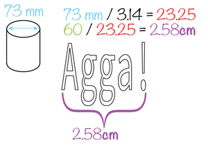
drawing width/(object diameter / 3.14)*10 = drawing width to use in autolaser
Example
Prepare laser
- Run the laser head to top right corner
- Lower the bed… a lot (U-)
- Move laser head approx half way on the y axis
- TURN OFF the laser before opening the the bottom panel on the right side of the laser
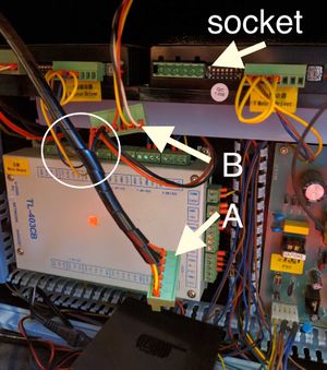
- Swap connectors behind the panel (see image).
- Basically: there are two connectors (A and B) attached to each other (or rather: they come out of the same twisty-cable-holder-thing), and one is plugged in to the socket.
- Swap them
- Close the lid
- ALWAYS PUT the normal one BACK when finished. If someone didn't attend the Rotary-attachment training, they'll have NO idea why the laser isn't working.
- Turn the laser on. It should now be unable to "home" normally (go to the top right corner), as one axis now is the rotary, but will "home" on the Y axis, sending the laser head all the way over to the right side.
Rotation max/min
Even if the rotary attachment has no physical endpoints, the laser control software will have a max/and min position. You will probably want to do your work while the laser is in the middle of these points. This can be achieved by rotating the attachment using the up/down button to one end, counting the number of seconds it takes to rotate all the way to the other end, and then rotating it back approx half as many seconds as a max-min-movement takes. If you try to range or start a job while the laser is to close to the max or min positions you will get a outbound (out of bounds) error on the display panel.
"Jaw"
Place the rotary axis attachment inside the laser
- Carefully place the rotary axis attachment inside the laser with the jaws (spindle, chuck, heavy end…) to the LEFT.
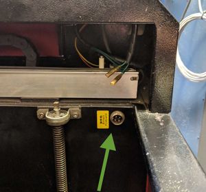
- Attach the coax cable from the rotary axis attachment to the connector inside the laser. When you stand in front of the laser, it is bottom right. The connector is marked with a yellow sticker: "rotary pinboard" (see image).
- From now on you must be VERY careful not to smash the laser head into stuff
Align the probe over the desired area and set focus point as normal, with .+enter.
To be super careful, drive the laser head away from the rotary axis attachment, and do a range test in an area where it will not smash into anything, should there be a … mishap. Pay careful attention to how the probe moves, and how the rotation moves. If it seems as expected, drive the laser head to the place where you want the job to begin. Note that you do not align with the probe, but the laser.
Glass surface: Preparation
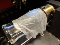
Using a moist paper towel helps prevent the engraving area from becoming rough, and leads to a clear, white engraving result. Before you start engraving, apply a moist single-layer paper towel to the glass. Make sure there are no air bubbles or overlaps. This would affect the engraved image.
We have so far had success with one ply from the two-ply towels from the bathrooms, damped liberally using a spray bottle (i.e. the fire-bottle in the laser room).
Do not spray water inside the laser.
Suggested settings
IKEA rødvinsglass, IKEA beer glass, IKEA tall beer glass raster: 100 mm/s 50%
